
IoT Smart Rainwater Harvesting System Using ESP32
Collects rainwater automatically and stops before the tank overflows.
Built and tested by Drisya K S · Industrial Robotics Institute
What is the IoT Smart Rainwater Harvesting System?
A smart rainwater harvesting controller. A rain sensor detects rainfall and the ESP32 switches on a pump to collect water into the storage tank. An ultrasonic sensor monitors the tank level; when it is full, the pump stops and a buzzer warns of overflow. Rain status, water level and system status are shown in the Blynk app.
How it works
- The rain sensor detects rainfall (output LOW).
- During rain, the relay turns the pump on to collect water.
- The ultrasonic sensor measures the distance down to the water in the tank.
- When the water is within 10 cm of the top, the pump stops and the buzzer sounds.
- Rain, water level and status go to Blynk V1, V2 and V3.
Parts list
| Component | Qty |
|---|---|
| ESP32 Dev Board | 1 |
| Rain Sensor Module | 1 |
| Ultrasonic Sensor (HC-SR04) | 1 |
| Water Pump | 1 |
| Relay Module | 1 |
| Float Sensor (optional backup) | 1 |
| Buzzer | 1 |
| LED | 1 |
| Jumper Wires / Breadboard | As needed |
| Power Supply | 1 |
Software
- Arduino IDE
- Blynk IoT app
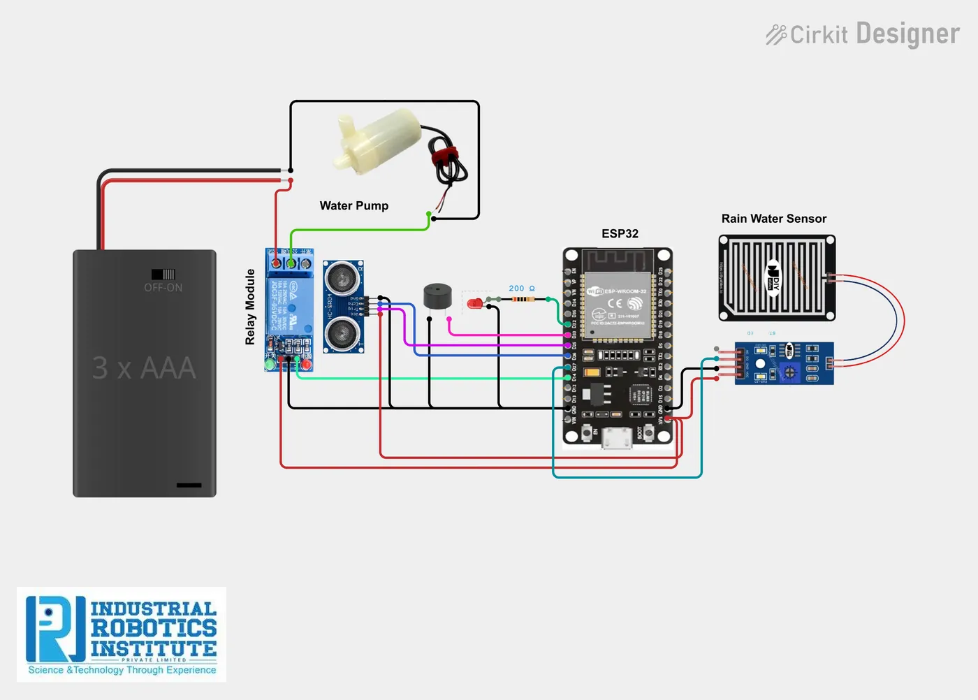
Wiring and connections
| From | Connect to |
|---|---|
| Rain sensor VCC | 3.3V |
| Rain sensor GND | GND |
| Rain sensor DO | GPIO 27 |
| Ultrasonic VCC | 5V |
| Ultrasonic GND | GND |
| Ultrasonic TRIG | GPIO 25 |
| Ultrasonic ECHO | GPIO 26 (via divider to 3.3V) |
| Relay IN | GPIO 14 |
| Relay VCC / GND | 5V / GND |
| Pump | Through relay COM / NO |
| Buzzer + | GPIO 33 |
| LED + (via resistor) | GPIO 32 |
How to build the IoT Smart Rainwater Harvesting System
- Place the rain sensor board outdoors and the ultrasonic sensor at the top of the tank, facing down.
- Wire the sensors, relay, buzzer and LED as in the table; use a voltage divider on ECHO.
- Connect the pump to its supply through the relay.
- In Blynk, create datastreams V1 rain, V2 water level and V3 status, with a gauge and label.
- Add your Blynk details and Wi-Fi and upload the code.
- Set the "tank full" distance (10 cm) for your tank.
IoT Smart Rainwater Harvesting System code
Complete, tested Arduino C++ code for this project. Copy it into Arduino IDE and upload it to the ESP32.
#define BLYNK_TEMPLATE_ID "YourTemplateID"
#define BLYNK_TEMPLATE_NAME "Rainwater Harvesting"
#define BLYNK_AUTH_TOKEN "YourAuthToken"

#include <WiFi.h>
#include <BlynkSimpleEsp32.h>

char ssid[] = "YourWiFiName";
char pass[] = "YourWiFiPassword";

#define rainPin  27
#define trigPin  25
#define echoPin  26
#define relayPin 14
#define buzzer   33

long duration;
int distance;

void setup() {
  Serial.begin(115200);
  pinMode(rainPin, INPUT);
  pinMode(trigPin, OUTPUT);
  pinMode(echoPin, INPUT);
  pinMode(relayPin, OUTPUT);
  pinMode(buzzer, OUTPUT);
  Blynk.begin(BLYNK_AUTH_TOKEN, ssid, pass);
}

void loop() {
  int rain = digitalRead(rainPin);     // LOW = rain

  digitalWrite(trigPin, LOW);
  delayMicroseconds(2);
  digitalWrite(trigPin, HIGH);
  delayMicroseconds(10);
  digitalWrite(trigPin, LOW);
  duration = pulseIn(echoPin, HIGH);
  distance = duration * 0.034 / 2;

  Blynk.virtualWrite(V1, rain);
  Blynk.virtualWrite(V2, distance);

  if (distance < 10) {                 // tank full
    digitalWrite(relayPin, LOW);       // pump OFF
    digitalWrite(buzzer, HIGH);
    Blynk.virtualWrite(V3, "Tank Full - Pump OFF");
  } else {
    digitalWrite(buzzer, LOW);
    if (rain == LOW) {
      digitalWrite(relayPin, HIGH);    // pump ON
      Blynk.virtualWrite(V3, "Rain Detected - Collecting Water");
    } else {
      digitalWrite(relayPin, LOW);
      Blynk.virtualWrite(V3, "No Rain - Standby");
    }
  }

  Blynk.run();
  delay(1000);
}
Real-world uses
- Homes and apartments
- Schools and offices
- Farms
- Water conservation projects
Frequently asked questions
What is a IoT Smart Rainwater Harvesting System?
A smart rainwater harvesting controller. A rain sensor detects rainfall and the ESP32 switches on a pump to collect water into the storage tank.
What components are needed for the IoT Smart Rainwater Harvesting System?
You need: ESP32 Dev Board (1), Rain Sensor Module (1), Ultrasonic Sensor (HC-SR04) (1), Water Pump (1), Relay Module (1), Float Sensor (optional backup) (1), Buzzer (1), LED (1), Jumper Wires / Breadboard, Power Supply (1). Software: Arduino IDE, Blynk IoT app.
Is the IoT Smart Rainwater Harvesting System project good for beginners?
It is rated intermediate and takes about 3–4 hours to build, using the ESP32. The guide on this page explains every connection and step.
Where can I get the code for the IoT Smart Rainwater Harvesting System?
The complete, tested Arduino C++ code is free on this page. Copy it into Arduino IDE and upload it to the board.
Can I buy a kit for the IoT Smart Rainwater Harvesting System?
Yes. IRI sells a kit with the parts for this project (PRJ-156). Message IRI on WhatsApp at +91 86060 82634 for the kit price and delivery details.