
Line Follower Robot Using Arduino
An autonomous robot that follows a black line using two IR sensors.
Built and tested by Anju.A · Industrial Robotics Institute
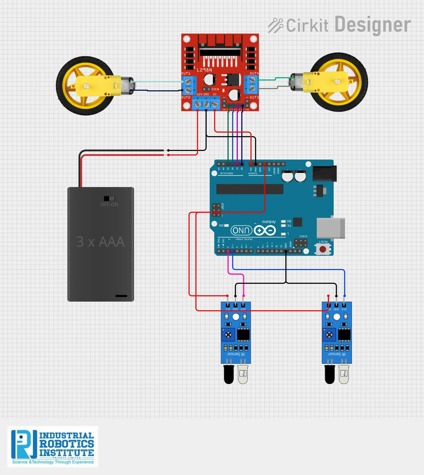
What is the Line Follower Robot?
A line follower robot is an autonomous robot that follows a path drawn on the floor, usually a black line on a white surface. Two IR sensors detect the line and an Arduino Uno controls the motors through an L298N driver. When the robot drifts off the line, the sensors detect the change and the Arduino adjusts the motors to bring it back.
How it works
- Two IR sensors are mounted at the front: one on the left and one on the right of the line.
- When both sensors see the white surface, both motors run forward.
- When the left sensor sees the black line, the left motor reverses and the right motor runs forward, turning the robot left.
- When the right sensor sees the black line, the robot turns right in the same way.
- When both sensors see black, all motor pins go LOW and the robot stops.
Parts list
| Component | Qty |
|---|---|
| Arduino Uno | 1 |
| IR Sensor Module | 2 |
| L298N Motor Driver | 1 |
| BO Gear Motor | 2 |
| Robot Chassis | 1 |
| Wheels and Caster Wheel | 1 set |
| 18650 Lithium Battery | 2 |
| 2-Cell 18650 Battery Holder with Switch | 1 |
| Jumper Wires | As needed |
Software
- Arduino IDE
Wiring and connections
| From | Connect to |
|---|---|
| Left IR VCC | 5V |
| Left IR GND | GND |
| Left IR OUT | Arduino Pin 2 |
| Right IR VCC | 5V |
| Right IR GND | GND |
| Right IR OUT | Arduino Pin 3 |
| L298N IN1 (Left Motor) | Arduino A0 |
| L298N IN2 (Left Motor) | Arduino A1 |
| L298N IN3 (Right Motor) | Arduino A2 |
| L298N IN4 (Right Motor) | Arduino A3 |
| Battery + | L298N 12V |
| Battery – | L298N GND |
| Arduino GND | L298N GND |
How to build the Line Follower Robot
- Mount the two BO gear motors, wheels and caster wheel on the robot chassis.
- Fix the two IR sensors at the front of the chassis, one on each side of the line.
- Connect the motors to the L298N outputs and wire IN1–IN4 to Arduino pins A0–A3.
- Wire the left IR sensor OUT to pin 2 and the right IR sensor OUT to pin 3, with VCC to 5V and GND to GND.
- Connect the 2-cell 18650 battery holder to the L298N 12V and GND terminals, and tie Arduino GND to L298N GND.
- Upload the code to the Arduino Uno using the Arduino IDE.
- Place the robot on a black line track on a white surface and switch it on to test.
Line Follower Robot code
Complete, tested Arduino C++ code for this project. Copy it into Arduino IDE and upload it to the Arduino Uno.
int leftSensor = 2;
int rightSensor = 3;

int LM1 = A0;
int LM2 = A1;
int RM1 = A2;
int RM2 = A3;

void setup()
{
  pinMode(leftSensor, INPUT);
  pinMode(rightSensor, INPUT);

  pinMode(LM1, OUTPUT);
  pinMode(LM2, OUTPUT);
  pinMode(RM1, OUTPUT);
  pinMode(RM2, OUTPUT);
}

void forward()
{
  digitalWrite(LM1, HIGH);
  digitalWrite(LM2, LOW);
  digitalWrite(RM1, HIGH);
  digitalWrite(RM2, LOW);
}

void left()
{
  digitalWrite(LM1, LOW);
  digitalWrite(LM2, HIGH);
  digitalWrite(RM1, HIGH);
  digitalWrite(RM2, LOW);
}

void right()
{
  digitalWrite(LM1, HIGH);
  digitalWrite(LM2, LOW);
  digitalWrite(RM1, LOW);
  digitalWrite(RM2, HIGH);
}

void stopRobot()
{
  digitalWrite(LM1, LOW);
  digitalWrite(LM2, LOW);
  digitalWrite(RM1, LOW);
  digitalWrite(RM2, LOW);
}

void loop()
{
  int leftValue = digitalRead(leftSensor);
  int rightValue = digitalRead(rightSensor);

  if (leftValue == HIGH && rightValue == HIGH)
  {
    forward();
  }
  else if (leftValue == LOW && rightValue == HIGH)
  {
    left();
  }
  else if (leftValue == HIGH && rightValue == LOW)
  {
    right();
  }
  else
  {
    stopRobot();
  }
}
Real-world uses
- Industrial automation
- Warehouse material transport
- Automated transportation systems
Frequently asked questions
What is a Line Follower Robot?
A line follower robot is an autonomous robot that follows a path drawn on the floor, usually a black line on a white surface. Two IR sensors detect the line and an Arduino Uno controls the motors through an L298N driver.
What components are needed for the Line Follower Robot?
You need: Arduino Uno (1), IR Sensor Module (2), L298N Motor Driver (1), BO Gear Motor (2), Robot Chassis (1), Wheels and Caster Wheel (1 set), 18650 Lithium Battery (2), 2-Cell 18650 Battery Holder with Switch (1), Jumper Wires. Software: Arduino IDE.
Is the Line Follower Robot project good for beginners?
Yes. It is rated beginner and takes about 2–3 hours to build, using the Arduino Uno. The guide on this page explains every connection and step.
Where can I get the code for the Line Follower Robot?
The complete, tested Arduino C++ code is free on this page. Copy it into Arduino IDE and upload it to the board.
Can I buy a kit for the Line Follower Robot?
Yes. IRI sells a kit with the parts for this project (PRJ-007). Message IRI on WhatsApp at +91 86060 82634 for the kit price and delivery details.