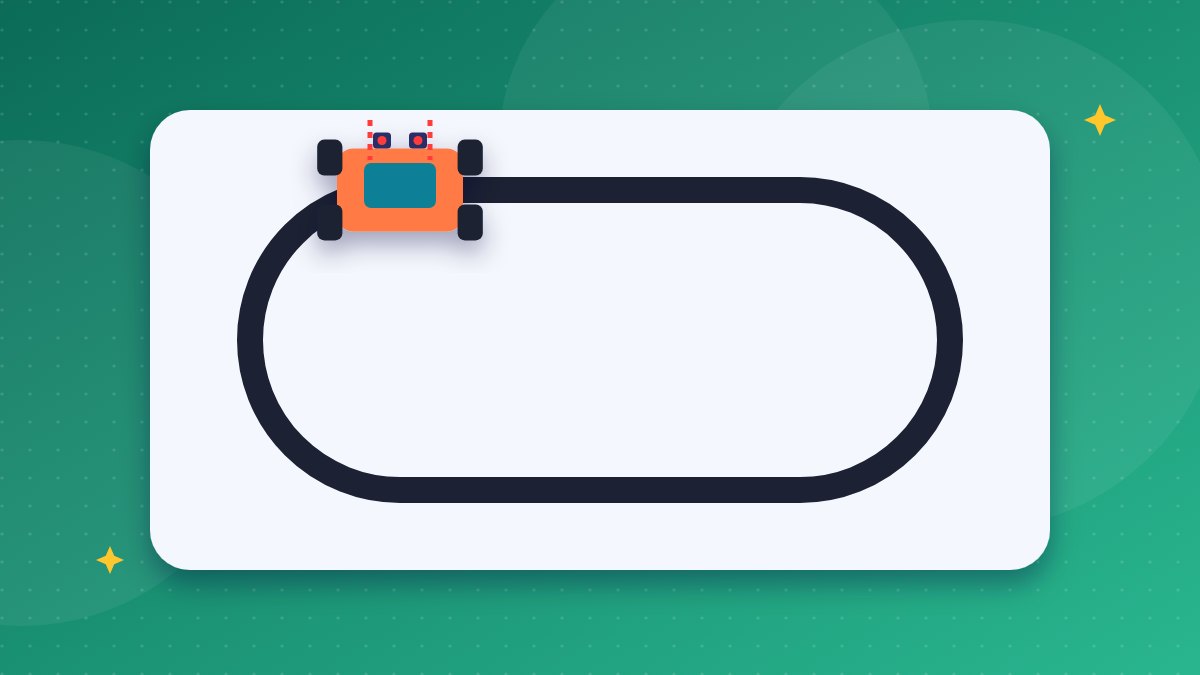
A line follower robot is a small vehicle that tracks a black line on a white surface by itself. It is one of the best first builds in robotics because it brings sensors, logic and motors together in one weekend. In this guide we explain how a line follower robot using Arduino works, list the parts, summarise the wiring, and share a short program your students can upload and test. It is a reliable robotics project for students in school or at home.
How an IR Sensor Robot Project Sees the Line
The robot “sees” the track using infrared (IR) sensor modules. Each module has two parts facing the floor: an IR LED that sends out invisible light, and a photodiode that receives the light that bounces back.
A white surface reflects most of the IR light, so the receiver gets a strong signal. A black surface absorbs most of it, so very little light returns. A small comparator chip on the module (usually the LM393) turns this difference into a clean digital output: HIGH or LOW. A small potentiometer on the module lets you adjust the sensitivity for your floor and lighting.
On most low-cost modules, the output goes LOW when light is reflected (white) and HIGH when it is absorbed (black). Some modules work the other way round, so always test yours first. Hold the sensor over white paper and then over black tape, and watch the onboard indicator LED or print the value to the Serial Monitor.
The Logic Table
We place two sensors at the front of the robot, one on each side of the black line. When the robot is centred, both sensors look at white. When it drifts, one sensor moves over the line and the robot corrects itself.
| Left sensor | Right sensor | What it means | Action |
|---|---|---|---|
| White (LOW) | White (LOW) | Line is between the sensors | Move forward |
| Black (HIGH) | White (LOW) | Robot drifted right | Turn left |
| White (LOW) | Black (HIGH) | Robot drifted left | Turn right |
| Black (HIGH) | Black (HIGH) | Junction or end of track | Stop |
This table is the whole “brain” of the robot. Students can write it on paper first, then turn each row into an if statement in code.
Components You Need
- Arduino Uno: the microcontroller that reads the sensors and decides the action.
- 2 IR sensor modules: digital output type with a sensitivity potentiometer.
- L298N motor driver: the Arduino pins cannot supply enough current for motors, so the driver acts as a power switch controlled by the Arduino.
- 2 BO motors with wheels: small geared DC motors, common in school kits.
- Chassis with a caster wheel: acrylic or plastic base to hold everything.
- Battery: a 7.4 V Li-ion pack or a holder with rechargeable cells, plus a switch.
- Jumper wires, screws and black electrical tape for the track.
Wiring Summary
- Sensors: connect VCC of both modules to Arduino 5V and GND to GND. Connect the left sensor OUT to pin 2 and the right sensor OUT to pin 3.
- Motors: connect the left motor to the OUT1 and OUT2 terminals of the L298N, and the right motor to OUT3 and OUT4.
- Driver control: connect IN1, IN2, IN3 and IN4 to Arduino pins 5, 6, 9 and 10. Leave the ENA and ENB jumpers in place for full speed, or remove them and connect to PWM pins if you want speed control later.
- Power: connect the battery positive to the 12V input of the L298N and the negative to its GND. With the 5V regulator jumper fitted and a battery under 12 V, the L298N’s 5V terminal can power the Arduino through its 5V pin.
- Common ground: make sure the Arduino GND and the L298N GND are connected. A missing common ground is the most frequent reason a robot does not respond.
Mount the sensors about 1 to 2 cm above the floor and slightly wider apart than the line. A line made with 18 to 20 mm electrical tape works well.
Arduino Code
This simple program follows the logic table exactly. It uses digital on and off control, which is easy to understand for beginners.
// Two-sensor line follower (black line on white floor)
const int LS = 2;   // left IR sensor OUT
const int RS = 3;   // right IR sensor OUT
const int IN1 = 5, IN2 = 6;   // left motor
const int IN3 = 9, IN4 = 10;  // right motor

void setup() {
  pinMode(LS, INPUT);
  pinMode(RS, INPUT);
  pinMode(IN1, OUTPUT); pinMode(IN2, OUTPUT);
  pinMode(IN3, OUTPUT); pinMode(IN4, OUTPUT);
}

void drive(int a, int b, int c, int d) {
  digitalWrite(IN1, a); digitalWrite(IN2, b);
  digitalWrite(IN3, c); digitalWrite(IN4, d);
}

void loop() {
  int L = digitalRead(LS);   // HIGH = sees black on most modules
  int R = digitalRead(RS);

  if (L == LOW && R == LOW)        drive(HIGH, LOW, HIGH, LOW); // forward
  else if (L == HIGH && R == LOW)  drive(LOW, LOW, HIGH, LOW);  // turn left
  else if (L == LOW && R == HIGH)  drive(HIGH, LOW, LOW, LOW);  // turn right
  else                             drive(LOW, LOW, LOW, LOW);   // stop
}
If a motor spins backwards, swap its two wires at the driver terminal or swap the HIGH and LOW values for that motor in the code. If your sensors give the opposite readings, swap LOW and HIGH in the conditions.
Testing and Tuning Tips
- Lift the robot off the floor and test each motor direction before running it on the track.
- Adjust each sensor potentiometer until the indicator LED switches cleanly between the tape and the floor.
- Start with gentle curves. Sharp turns need slower speed, so later you can add PWM speed control on ENA and ENB.
- Avoid strong sunlight on the track, because sunlight contains IR and can confuse the sensors.
Once the basic robot works, students can add a third centre sensor, PWM speed control, or an ultrasonic sensor to stop for obstacles. Warehouses use the same idea in automated guided vehicles that follow lines on the floor.
Key takeaways
- IR sensors detect the line because white reflects infrared light and black absorbs it.
- Two sensors and a four-row logic table are enough to steer the robot.
- The L298N driver supplies motor current; the Arduino only sends control signals.
- A common ground and correctly tuned sensors solve most problems.
- The project grows naturally into speed control and smarter algorithms.
Build Robots Every Week with IRI
Industrial Robotics Institute runs a Robotics & AI pathway for Class 1 to 12, built on our own grade-wise textbook series and aligned with NEP 2020. Students attend weekly hands-on classes with real kits and move from ScratchJr and Scratch to Tinkercad, Arduino, sensors, ESP32, IoT and Python. Projects like the line follower are part of that journey. We have trained over 60,000 learners and set up more than 180 Robotics & AI labs in schools. Ask us for a free 1 to 2 hour demo class on your campus. Call 8606082634 or email inrobos@gmail.com.
Weekly hands-on classes for Class 1–12 on IRI's own textbook series. Start with a free demo class on your campus.
Call 8606082634 · inrobos@gmail.com
Frequently asked questions
Which class is the right age to build a line follower robot?
Students in Class 6 and above can usually build and code it with guidance. Younger students can assemble the chassis and understand the logic table while a teacher handles the wiring.
Why does my line follower robot go off the track on curves?
It is usually moving too fast or the sensors are too close together. Reduce speed using PWM on the ENA and ENB pins, adjust sensor spacing, and retune the potentiometers.
Can I use the L298N to power the Arduino?
Yes. With the 5V regulator jumper fitted and a battery below 12 V, connect the L298N 5V terminal to the Arduino 5V pin and join both grounds.